

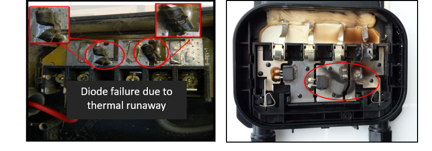
Advances in photovoltaic technology are closely related to improvements in module efficiency. As a result of intense market competition, module current has increased significantly over recent years. However, it should also be noted that module reliability has an impact on the operation of a power plant, meaning that reasonable parameters should be considered in terms of module design. A typical example is that when the current of a module reaches 18A~20A, electrical safety risks increase. In extreme cases, the junction box, backsheet and other materials may be damaged, or even catch fire, bringing potentially substantial losses to the plant.
1. IEC standard for module junction boxes and advantage of Hi-MO 5
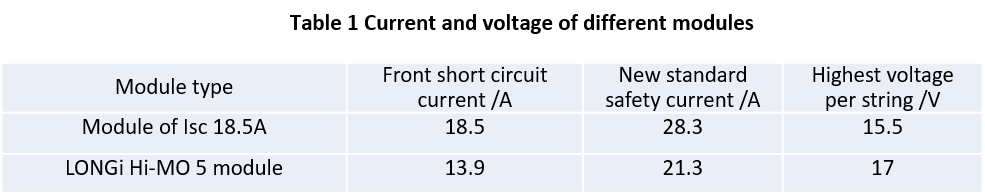
Modules and junction boxes are certified according to IEC 61215 and 62790 standards, which involve hot spot durability and diode thermal performance testing. After the release of the latest IEC 61215 standard, the calculation of safe current levels has needed to include consideration of bifacial gains. The formula is as follows. The current and voltage corresponding to different types of module are shown in Table 1. Hi-MO 5, with a 25A junction box, has been designed with adequate safe margin in terms of current. In contrast, a bifacial module with an Isc of 18.5A will need a junction box with a rated current of more than 30A to meet the requirements.

Where φ is the bifacial ratio of the module, generally 75%, and 1.25 the safety factor
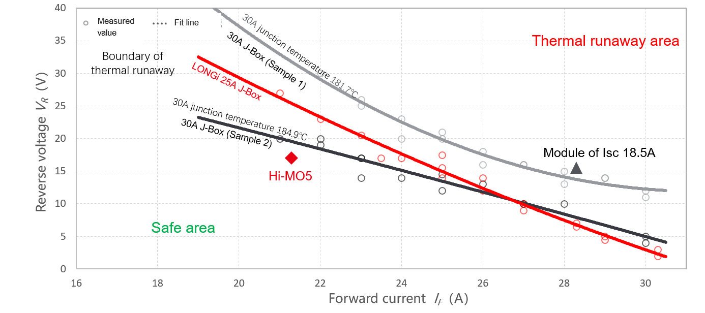
In addition, diodes carry a risk of thermal runaway when a module is operating outdoors. However, the related IEC 62979 standard is not a mandatory certification. Even if some junction boxes are able to pass IEC 61215 and 62790 testing, they may still not meet safety requirements for outdoor use. As illustrated in Figure 2, the stable 25A junction box keeps LONGi’s Hi-MO 5 module within the safe area but, in the case of a module of Isc 18.5A, two commercially available 30A junction boxes carry a risk of thermal runaway and neither is able to meet the requirements for long-term reliable use due to technical limitations.
2. The mechanism behind diode thermal runaway
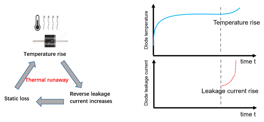
Hot spots occur when modules are shaded outdoors, with thermal runaway generally caused by instantaneous hot spots. When there are fallen leaves or dust covering a module, the diode is forward conducting but, when the covering is removed, the diode is reverse blocked. Ultra-high current or voltage of a module may lead to substantial instantaneous heating power. If the heat dissipation capability of the diode is weak, the heat cannot be dissipated in time and the thermal balance is compromised. The rising temperature causes higher current leakage, which in turn will result in a temperature increase - this vicious circle is thermal runaway.
3. Factors influencing thermal runaway
Based on the above mechanism, thermal runaway is related to forward current and reverse voltage. A controlled variable experiment was conducted to study the effect of these two factors on thermal runaway. As shown in figure 4, under the same forward current, reducing reverse voltage can reduce the risk of diode thermal runaway. Under the same reverse bias voltage, reducing forward current can also reduce this risk. In summary, the unilateral pursuit of high power can lead to ultra-high module current and the large number of cells in a single string can lead to an excessively high voltage corresponding to the module, which can significantly increase risk of thermal runaway.
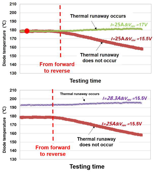
4b. Influence of forward current on thermal runaway of junction box under the same reverse voltage
In summary, LONGi’s Hi-MO 5 has advantages in terms of design, with a safe margin for module current preventing thermal runaway. The current and voltage of a photovoltaic module need to be controlled within a reasonable range, otherwise thermal stress on the diode may exceed its junction temperature limit, causing irreversible damage to the module. Although some hidden dangers have not been identified in the short term, they nevertheless have a key impact on the long-term safety and reliability of a module and on the profitability of a power plant.
About LONGi
Founded in 2000, LONGi is committed to being the world’s leading solar technology company, focusing on customer-driven value creation for full scenario energy transformation.
Under its mission of 'Utilizing Solar Energy, Building a Green World' and brand philosophy of 'Steadfast and Reliable Technology Leadership', LONGi has dedicated itself to technology innovation and established five business sectors, covering mono silicon wafers, cells and modules, commercial & industrial distributed solar solutions, green energy solutions and hydrogen equipment. The company has honed its capabilities to provide green energy and has, more recently, also embraced green hydrogen products and solutions to support global zero carbon development. www.longi.com